Assembly Instructions

Please scroll down page for an enlarged version of assembly instructions.
Step by step
- You should have a FRONT, a BACK, 2 SIDES and 20 screws.
- Start by laying the top frame parts out on the floor.
- Each corner has been numbered - 1 screws into 1, 2 screws into 2, 3 screws into 3, 4 screws into 4, use 5 screws for each corner.
- The numbers face the inside of the frame.
- On a flat surface begin by assembling the BACK to a SIDE.
- Hold the corner joint together in an upright position (the notched corners are on the bottom edge).
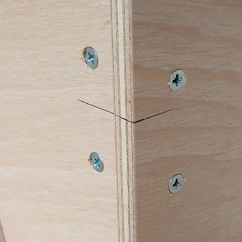
- Connect the 2 assembly lines together then put in the screws. All the holes have been prescrewed so the screws should go in easily if not recheck alignment lines.
- Next connect the other SIDE to the BACK.
- Now you should have a U shape of 2 SIDES and a BACK connected together.
- Lay the FRONT part onto a flat surface.
- Position the 2 SIDE corners onto the FRONT part. Connect the 2 assembly lines of 1 corner then put in the screws. Repeat for the other corner.
- The top frame is now ready to use.
- PLEASE NOTE - if you ordered a top frame with a tool box that the assembly procedure is as exactly the same as described above.
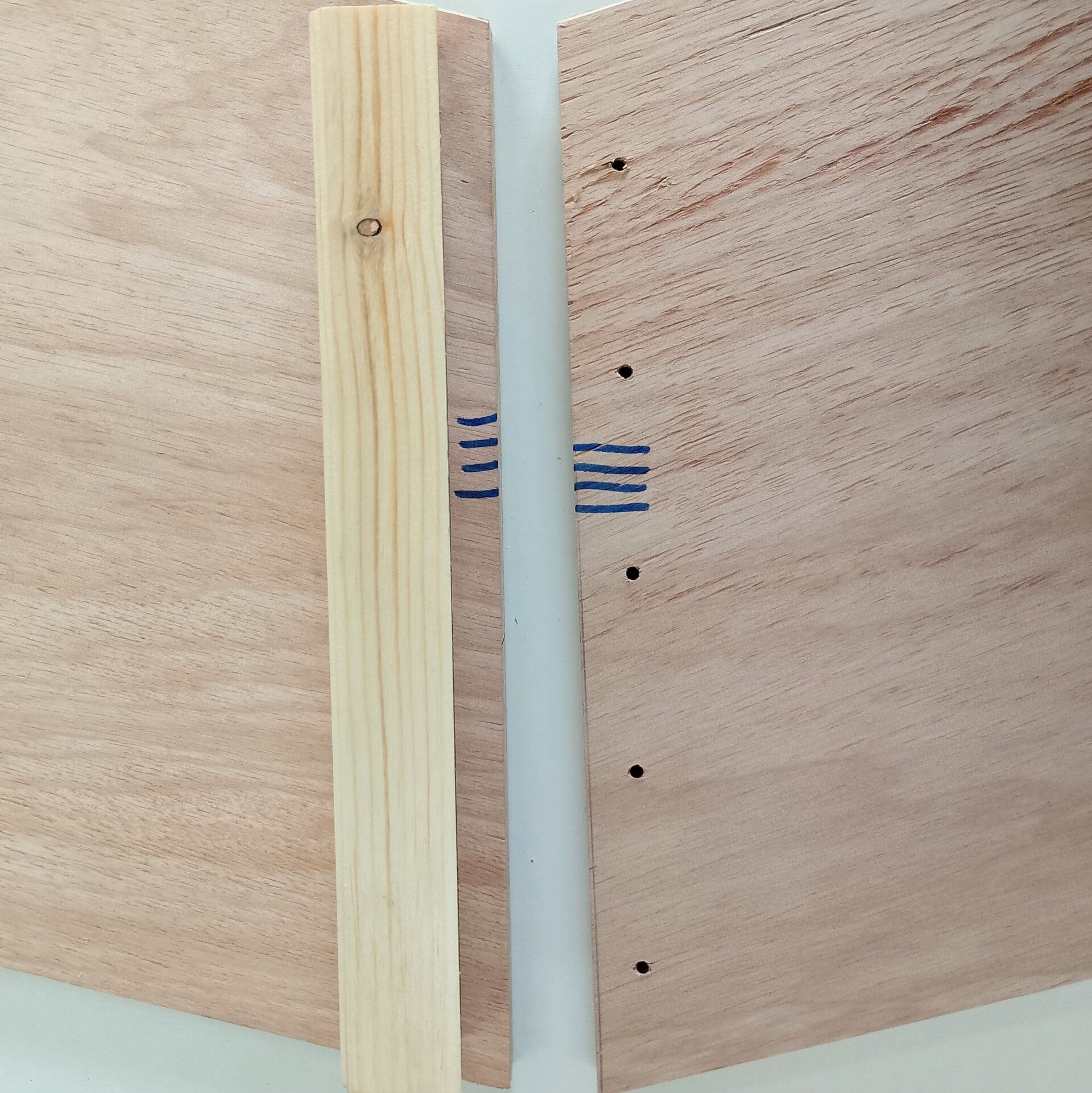
Photo above clearly shows corner joint numbers, 4 joins to 4, 3 to 3, 2 to 2, 1 to 1.
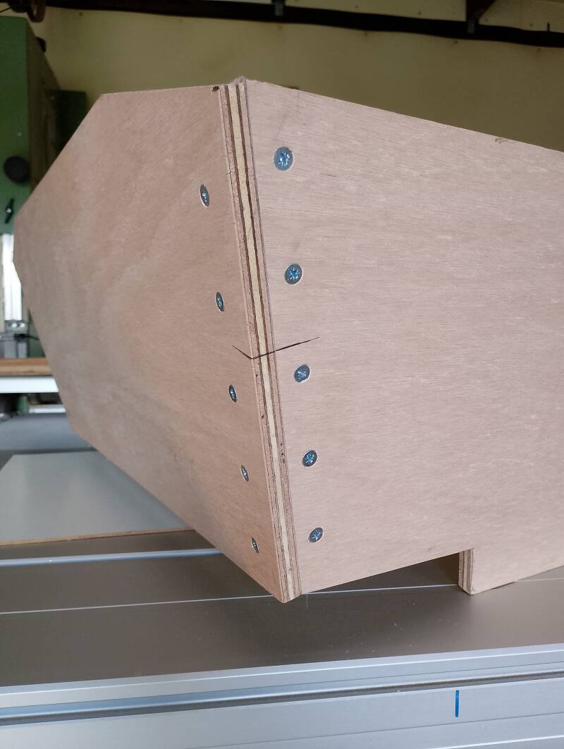
Photo above and below show corner assembly lines connected and in alignment.
How to use
Lift the top frame onto your wheelbarrow bowl. The BACK goes to the wheelbarrow bowl end with the handles. The BACK and the 2 SIDES fit inside the wheelbarrow bowl. The top frame should be resting on top of your wheelbarrow bowl at the corners.
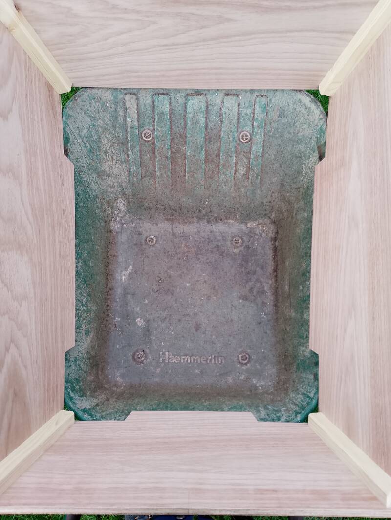
Photo above view of a top frame on top of wheelbarrow bowl.
The top frame requires no further attachment. Please ensure that the BACK of the top frame touches the back of the wheelbarrow bowl. You might have to push down onto the top frame to seat it properly.
If the top frame does not fit please check your wheelbarrow bowl to see if it is damaged. Has it been knocked out of shape? You might need to persuade it back into shape.
Enlargement of assembly instructions diagrams
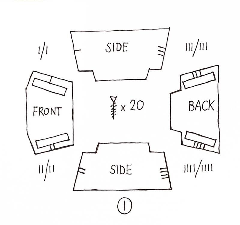
Layout parts - corner joints are numbered.
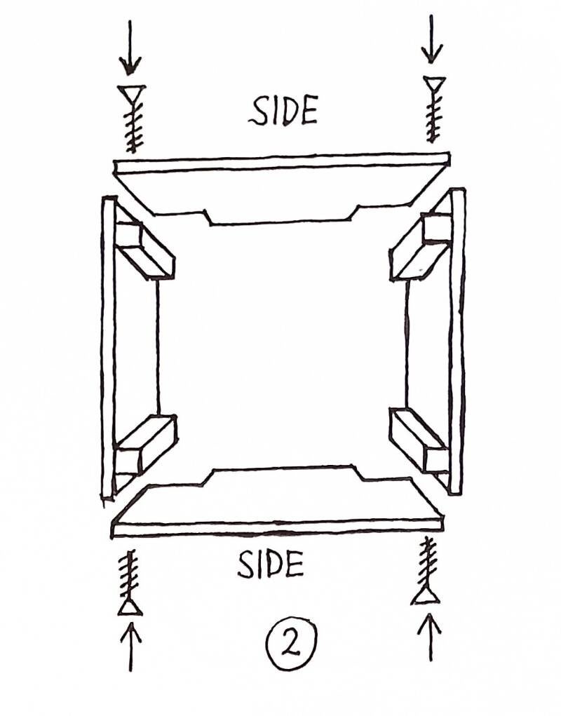
Sides screw into front and back.
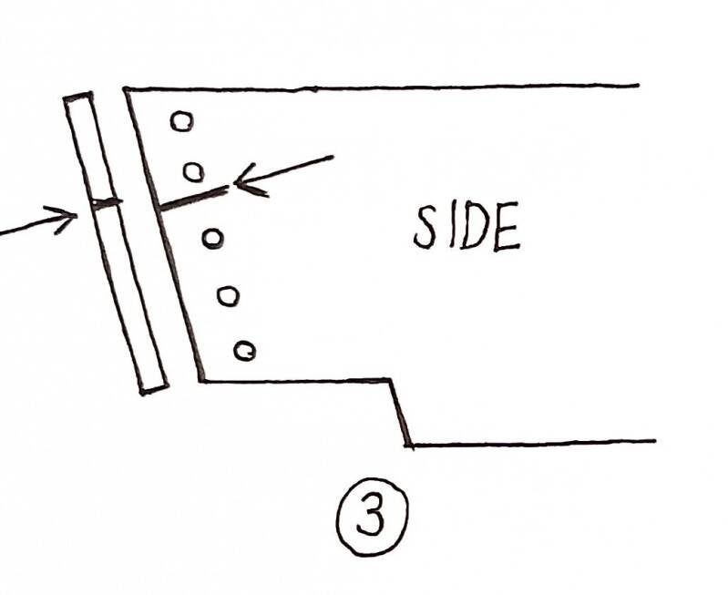
Corner assembly lines.
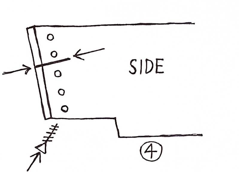
Connect corner assembly lines then put in screws.
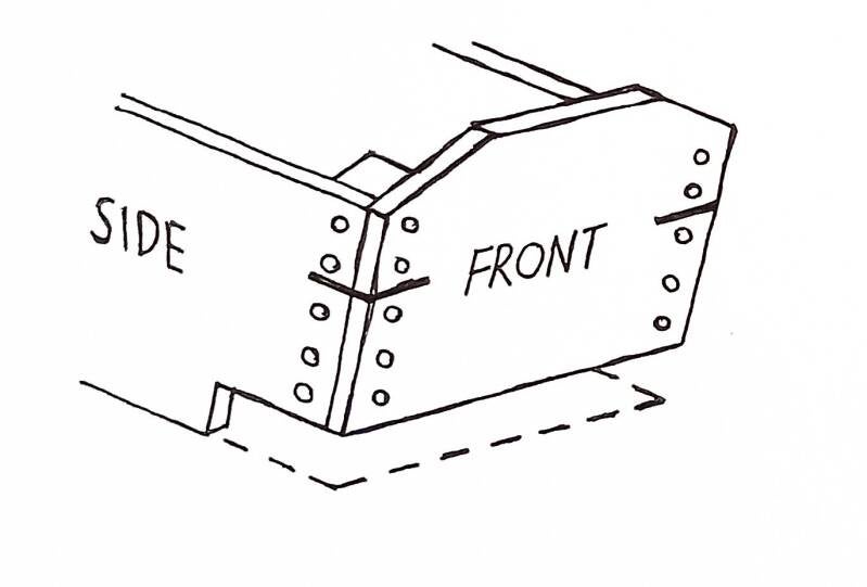
View of front to side.
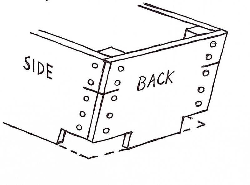
View of back to side.